![/(electr[^s]*)|(prog[^s]*)/](https://geekodercom.files.wordpress.com/2021/04/08deb-geekoder-1.gif?w=275)
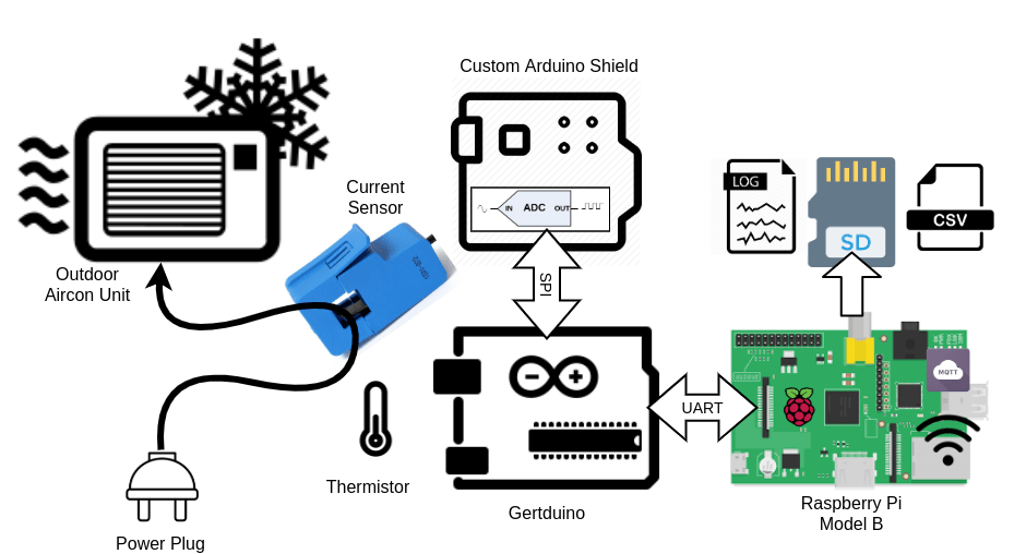
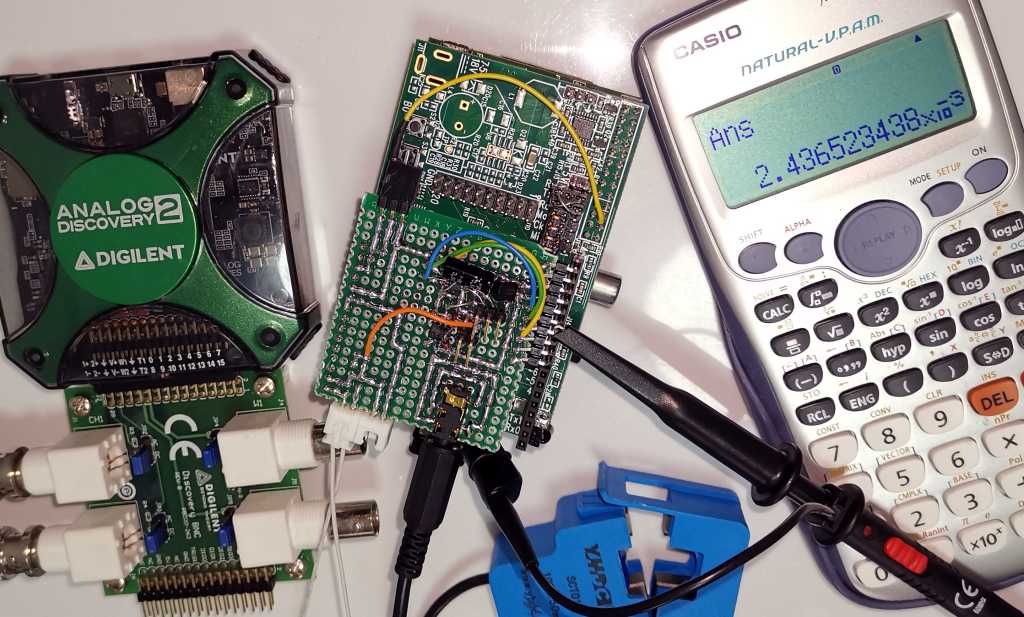
This is the second part of a multiple part series about some hardware & software that I hacked together to monitor the AC current of our outdoor aircon unit. This part I’ll be discussing how I’ve established the hardware parts selection for this project, which are SCT013 Current Sensor, SAR ADC, thermistor, Gertduino, and Raspberry Pi Model B (rev 1).
- Part 1 – The introduction – Why, what & how
- Part 2 – The hardware – current sensor, thermistor, ADC & Arduino (You’re reading this)
- Part 3 – The circuit design – Analog, digital and data flow
- Part 4 – The firmware – Arduino, RMS calculation & Raspberry Pi’s UART
- Part 5 – The software – data collection, analysis & decision
- Part 6 – The solution – still unknown at this stage
To achieve what I outlined in Part 1, which the aircon is reporting overcurrent during a hot day, I’ll need to measure the AC current and the temperature continuously over time. To be able to capture the peak current, the time resolution would have to be reasonably small. Preferably multiple times within a single cycle of our AC here at 50Hz. The hardware should also be remotely accessible, hence Wifi connection is a must 🙂
AC current sensor
To measure AC current safely, I’ve already had a YHDC SCT-013-000, 100A model which should work well for this. So that’s settled. OpenEnergyMonitor project site has a good report on it and various tutorials on using it.
ADC (Analog-to-Digital Converter)
I wasn’t sure how much current I needed to measure. Considering the aircon is on a 15A plug, a range of 15A should be more than sufficient. The ATmega328P on the any of the Arduino board I have only had 10-bit ADC, which for a scale of 15A, I can get about 15mA of resolution. Typically analog circuits are going to be noisy, plus the noise from the switching power supply of the Pi, I’m going to lose 1 bit if I’m lucky, and likely 2 or more bits. That gives me a resolution of 58~117mA. Assuming if the aircon is drawing at 2A at equilibrium, that only gives me about 34 counts out of 8-bit. Designing a low noise circuit is going to be hard when using a perfboard.
I could upgrade to the built-in 12-bit ADC in Redbear DUO, which would give me a much more comfortable 136 assuming effective 10-bits. Since it’s a 3.3V board, I would have less room to work with on the analog front end using op-amp. If I choose to lower the max current, then I might not be able to capture the peak I intended. In the end, I decided to go with an external ADC, giving me more leeway in the design. As for the sample rate, I wanted to get a decent RMS current measurement, most material I could find online suggest at least 1000 samples/s. I decided to do 5000 samples/s, which gives me 50 samples per half cycle, that should be more than enough for the RMS calculation.
Since I don’t have any ADC here, so I sign up for Element14 Singapore. Fun fact, Element14 Malaysia and Singapore shared the same backend system. How I know? I can’t reuse my username from Malaysia ;). I looked for an ADC that runs on 5V with at least 14 bits and faster than 5ksps. Sorted by price, I found ADS8317 from TI, 16-Bit, 250kSPS SAR converter.
In the past I’ve always stayed with Sigma-delta converter, mainly for it’s linearity and higher resolution. For this, I needed something faster, accuracy is not as important, but the resolution is. So using SAR converter allows me to play with something new while having a bit of challenge.
A good challenge will give a better satisfaction at the end 🙂 I’ve also learnt that this particular SAR converter supports “short cyling”, which you can stop the converter once you have enough significant bits to know that you can skip the rest. The converter works in “successive-approximation”, it produces the bits as you read it. If you stop reading, it stop as well, hence “short” cycling. Although I don’t use this feature here, but it’s an interesting concept to learn, that save time and power whenever you know you don’t need the full 16-bits.
Temperature Sensor
I also wanted to hook up a few temperature sensors to monitor the outside temperature and the temperature near the compressor. I had a bunch of spare 10K NTC thermistors from my 3D printer, that should do the work with any of PIC/Arduino’s ADC.
Micro-controller/Micro-processor
I’ve been bringing my microcontroller/microprocessor boards from back home (Malaysia) whenever I go back to see my family. So I’m spoiled with choices from simple Arduino boards, plain PICs, ESP8266, ESP32, Redbear Duo, Omega2 to Pine64 & various generations of Raspberry Pi.
I’ve decided on Gertduino, an Arduino board that doubles as a Pi HAT, and Raspberry Pi Model B (the first version). I wanted something that can run python, which requires less effort and can be easily updated remotely while having enough storage to be left alone when I’m busy during the week. It doesn’t need much grunt work, so and older Pi suffice. The outdoor unit is near my housemate’s bedroom window, so a reliable design helps by giving him less interruption.
ESP8266 or Redbear Duo both can achieve the same thing, but I have experienced both crashes in a shorter period than the Pi. Not blaming the hardware, but rather the overall system allowing me to crash it with lousy code. The ESP will also require additional ADC for the thermistors. And I’m not fond of tinkering with C++ code when I do my analysis later. Python works best as I could transfer from Jupyter notebook to python script with little to no modification.
That’s all for this week. I’ve had this sitting in my draft for a while. I recently learnt from Coaching for Leaders that I need to have the “courage to be rubbish”, to keep posting consistently, which is what matters than to make sure everything is perfect. I’ll keep up with posting the next part within the next 2 weeks.